The Yakindu Statechart Tools are predestined to describe the behavior for a system and afterward generate code. The output code could be Java, C or C++. We would like to use the code generator in the context of embedded systems and so we decided to generate code for an Arduino Uno. Therefore we modified our statechart TrafficLight example and implemented some simple glue code to map the hardware timer and the I/O-ports. Furthermore, it was necessary to build a hardware controller that represents the traffic light and so we created a simple controller (it’s available as eagle plan in the appendix and could easily be reconstructed). The example is directly implemented for the AVR ATMEGA328P-PU processor (this one is on the Arduino Uno). It is possible to use the Arduino library to integrate this system, but we would like to support the whole AVR family and so it was the better way to use the AVR library directly. With this solution, the Yakindu SCT could be used on many AVR based processors.
To explore the example project, you have to go through some steps:
1. Environment
- Download the eclipse IDE with Yakindu SCT from our download section, or install the Yakindu SCT by using the Eclipse update manager (see: http://statecharts.org/download.html).
-
Install the AVR plugin for eclipse from
-
On Linux, install the AVR environment:sudo apt-get install avrdude binutils-avr gcc-avr avr-libc gdb-avr.
- Get the Arduino software from http://arduino.cc/en/Main/Software and build the necessary libArduinoCore.a. See http://playground.arduino.cc/Code/Eclipse#Arduino_core_library for a detailed description. Now set the include path to the Arduino specific header files and also to the libArduinoCore.a. The libArduinoCore.a should be stored in a folder called “lib” in the project directory. The include path should look like this:
/arduino-1.0.5/hardware/arduino/variants/mega
/arduino-1.0.5/hardware/arduino/cores/arduino -
Open Eclipse and import the ArduinoTrafficLight example project from our Git repository (https://github.com/Yakindu/statecharts/tree/master/). You can find this project in the archive folder. After importing the project, you have to check if the include path is set correctly for your system
-
Build the TrafficLight hardware controller (see circuit layout in the appendix) and connect the ports to the Arduino Uno
-
Next you have to generate the C++ code by using the TrafficLight.sgen (right-click on the file and then generate artifacts). Currently, there is an open issue and you have to fix it manually. Open the src-gen/sc_types.h file and change the datatype sc_integer from int32_t to uint32_t. That’s all. Next, compile the code. For this, you can use the icon with the small hammer in eclipse.
-
Last but not least you have to flash the compiled program on the processor by activating the AVR-icon.
Now you are able to use the generated code on the Arduino board. Feel free to modify the statechart model and test the behavior on the hardware platform.
2. Some explaining words to the code
There are three things you have to implement as glue code so that the Arduino works:
2.1 CycleRunner
The CycleRunner checks periodically for state changes. It uses timer0 to trigger a completion step periodically. An implementation could look like this:
/*
 * The cycleRunner uses timer0 for his cycle-time-calculation (every second)
 */
void CycleRunner::start(void){
 TCCR0B |= (1<<CS02) | (1<<CS00); // prescaler 1024 TCNT0 = 0; // Startvalue ->1s to overflow
 TIMSK0 |= (1<<TOIE0);
}

void CycleRunner::runCycle(void){
 trafficlight_runCycle(handle);
}
/*
* the cycleRunner is triggered by this timerinterrupt
*/
ISR(TIMER0_OVF_vect) {
 runCycleFlag = 1;
}
2.2 Timer and TimeEvent
The Timer class is a representation for the hardware timer and it is responsible for initializing the timer and raising TimeEvents. In this example, we are using timer1 from the Arduino to implement the reaction trigger timer. A TimeEvent is triggered when e.g. a transition time expired. There are situations where you have to use several parallel running timers thus it was required to store the time events in an array (see events array in Main.cpp). The Timer checks periodically every 10ms for expired time events and raises them if it’s necessary.
// Timer ISR that triggers checking for expired time events
ISR(TIMER1_OVF_vect) {
 TCNT1 = 64911; // startvalue for 10ms

 if ((counter++) >= timer->getTimerOverflowCount()) {
  counter = 0;
  timerRaiseEventFlag = 1;
 }
}


void Timer::raiseTimeEvent() {
 for(int i=0;igetTimeMs()/10) <= events[i]->getTimerOverflowCount()){
   trafficlight_raiseTimeEvent(sc_handle, events[i]->getEventId());
   events[i]->setTimerOverflowCount(0);
  }

  events[i]->setTimerOverflowCount(events[i]->getTimerOverflowCount() + 1);
 }
}
2.3 IO port mapping
At the moment it is necessary to map the IO ports by yourself. You have to define the port direction and define a method to change the signals. For example, you can map the red traffic light LED like this:
const uint8_t ledPinTrafficRed = DDB5; // the number of the red LED pin
DDRB |= (1 << ledPinTrafficRed);       // set out direction for this port
Now you are able to change the LED signal by using the getter method from the state machine interface:
setLight(PORTB, ledPinTrafficRed,
trafficlightIfaceTrafficLight_get_red(&handle));
3. Appendix
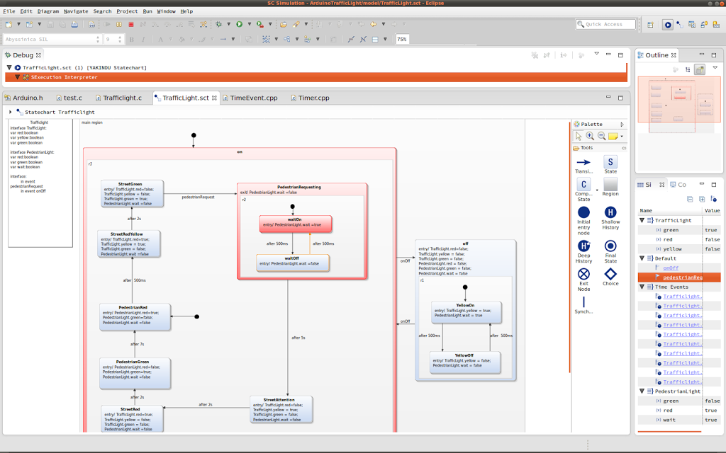
This movie demonstrates the traffic light with the statechart behavior. The designed model is shown in the following image.