TSL2561 light sensor implementation

  • Deutsch
  • English

The TSL2561 sensor measures the light-intensity and transforms it into a 16-bit resolution digital value. There are two photodiodes on the sensor, one to sense the light intensity plus infrared light and a second one to measure only infrared light. These two photodiodes convert the measured light-intensity simultaneously. There are two channels available on the sensor to transfer the values into the data register (channel 0 and channel 1). The idea is to subtract the infrared part of the light so that the resulting light spectrum is the human seeable light.

The measured data can be received via I2C or SMBus. In this article, the I2C bus will be for the communication between the STM32F4 and the the TSL2561.

Connect the device

The TSL2561 works with 3.8V, don’t use the 5V pin, you may destroy the sensor. Further, there are two pins (SDA and SCL) for the I2C bus communication. The SDA is the data line, while SCL is the clock. The address pin is to set a unique I2C bus address. The default address can be used unless there is another device with the same address on the bus. The default address is 0x39, but it can also be set to 0x29 or 0x49. The sensor can generate an interrupt so that it is not necessary to poll the device. In this example, the interrupt signal is not used.

TSL2561 light sensor

The software part

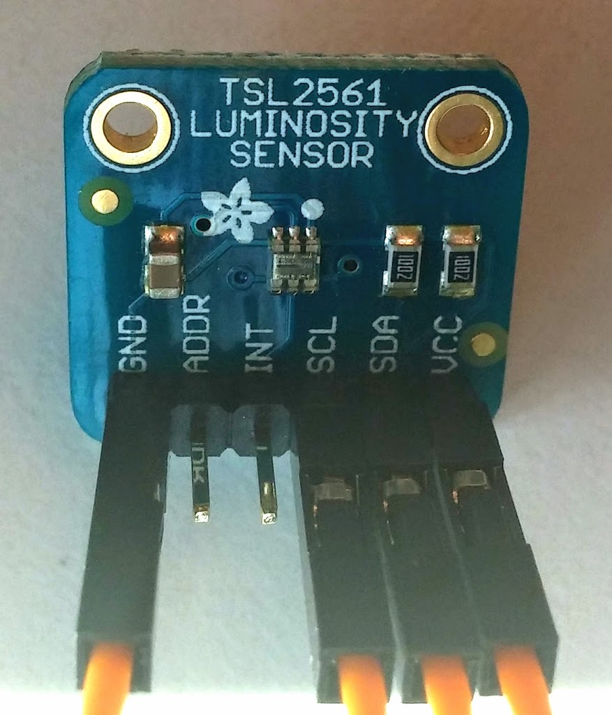
The STM32F4 controller has several I2C interfaces. The example implementation uses the I2C1, which is connected to GPIO6 (SCL) and GPIO7 (SDA). The configuration is encapsulated to a configuration header, so it is easy to change the bus. The software can be downloaded from the repository (the project is called TSL2561_example). The maximum clock frequency for the device is 400kHz, so this frequency is set in the configuration file. The init_lightsensor(void) method is configures the necessary IOs and the I2C communication via initLightSensorI2C(void).

To read the measured values, there are four registers (two for every channel), that can be read. First, there is an 8-bit register that contains the values low byte and then there is a second register for the high byte.

addressdescription
0x00control register
0x8Clow byte (channel0)
0x8Dhigh byte (channel0)
0x8Elow byte (channel1)
0x8Fhigh byte (channel1)

To read bytes from the device registers, the requested register addresses should be sent bytewise to the control register (0x00). There is a command bit that must be set so that the device reacts to the request.

The received data can be calculated to the SI unit LUX. This calculation is already implemented in the example code. The read_lightness_value() method receives the data bytes via I2C and processes the calculation to LUX.