STM32F4 controlled omnidirectional mecanum robot with odometry

STM32F4 controlled omnidirectional mecanum robot with odometry
  • Deutsch
  • English

In the last months, I worked on a new project based on an ARM STM32F4 controller. The goal was to implement a software to control a robot with mecanum wheels (also called Swedish wheels). These wheels are very special because there are rubber rollers arranged at 45 degrees on the outer rim that roll passively on the ground. Thus the robot has a further degree of freedom. This means all directions (X, Y, Θ) can be reached by the robot on a plane. Despite the lack of a steering axle, it has maximum freedom of movement. X and Y correspond to the movement in the respective directions, and Θ represents the rotational movement of the robot.

the robot

The robot is a Nexus 4WD. It has four Faulhaber motors which are directly equipped with incremental encoders furthermore it also has (ultrasonic) distance sensors and an Arduino controller with suitable motor drivers. The 12 V DC motors are powered by a battery that is connected with a standard Tamiya plug.
Since I have decided to use the STM32F4, I performed some modifications to the robot. In particular, the Arduino controller was replaced by the STM32F4, but this had the consequence that the motor drivers that were permanently installed on the board of Arduino, were also removed from the robot. Therefore, a new engine controller with appropriate drivers (h-bridge) had to be developed so that the motors can be controlled properly.  In addition to the existing sensors and actuators, the robot is equipped with a gyroscope so that the orientation, that is, the rotation movements of the robot, can be measured in the context of odometry.

Figure1 and figure2 are showing the robot with an open chassis. They also show the four Mecanum wheels which are fixed to the shafts of the motors. In addition, you can see – despite the bunch of wires – the hardware components and the battery. Figure2 shows the robot in a top view and figure3 shows the individual hardware highlighted.

Figure1: Nexus 4WD (back view)
Figure2: Nexus 4WD (top view)
Figure3: Nexus 4WD with highlighted hardware

The movement of the robot is omnidirectional and it depends on how the wheels are arranged and how they rotate. The mecanum wheels are so arranged that the rollers are arranged into the center of the vehicle (in perspective from above). Thus, the movement direction is defined by wheel movement. Figure4 shows three scenarios to illustrate how the directions of rotation of the wheels affect the movement of the robot. So you can see in example (a) that all the wheels rotate forward. The resulting movement of the robot is thus a forward movement. In example (b), the wheels turn in different directions. These on the left side of the robot rotate inwards while the wheels on the right side rotate outwards. The resulting movement is in the Y direction on a plane. In the third example, the wheels on the left side rotate backward while the wheels on the right side rotate forwards. This results in a counterclockwise rotation of the robot.

motor control

With the Arduino, the motor driver was also removed because they were mounted on the controller. Therefore, a board has been developed with two Toshiba TB6612FNG motor driver. This driver can handle two motors so that two pieces were used in total. The drivers are a little undersized because the engines are given a maximum current of 1.4A. Since the motor driver only withstands a maximum current of 1.2 A, the engine performance is limited to a maximum of 80% in the software. To control the driver (through the STM32F4) a PWM signal is generated by a timer. This signal causes the driver to create a corresponding voltage to the motors. So the timer generated PWM signal influences the power of the motors

Figure 4: robot motion depending on the rotational direction of the mecanum wheels

incremental encoder​

Incremental encoders are sensors for measuring rotations. With the use of a timer, is possible to measure the angular velocity of a rotation. The angle can be calculated by integration over time. Because of the fixed radius of the wheels, the driven distance can be determined by the multiplication of the angle and the radius.

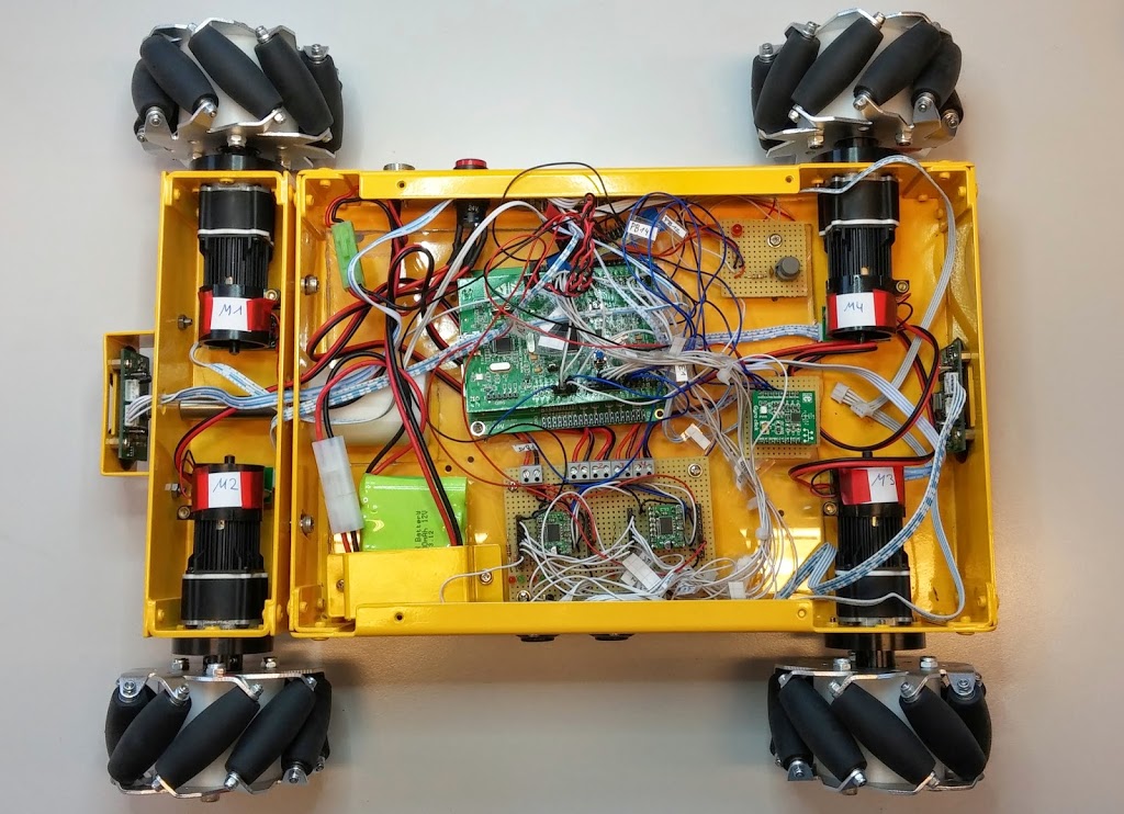
The Nexus robot has four photoelectric incremental encoders, which generates 12 pulses per rotation. The photoelectrical encoder emits a light pulse through a rotating disc, which has a couple of slits. Thus, a periodic signal is generated, which allows concluding the velocity and the direction of a wheel. This signal is getting interpreted by the STM32F4 controller and processed by the software. The rotations of the motors are transmitted by a gear with a ratio of 64:1. So the count of the pulses is increased to 768 pulses per rotation. The STM32F4 controller has quadrature encoders, so the steps per rotation are again increased by factor four to 3072 in total. Thus, the resolution of the incremental encoder is approximately 0.117°.

The following example shows the initialization of an encoder as a quadrature encoder:

void initEncoders(fahrzeug_t *fz) {  
      fz->encoder[0].id = ENCODER_1;  
      fz->encoder[0].direction = FORWARD;  
      GPIO_InitTypeDef GPIO_InitStructure;  
      // Takt fuer die Ports einschalten  
      RCC_AHB1PeriphClockCmd(ENC1A_GPIO_CLK, ENABLE);  
      RCC_AHB1PeriphClockCmd(ENC1B_GPIO_CLK, ENABLE);  
      GPIO_StructInit(&GPIO_InitStructure);  
      GPIO_InitStructure.GPIO_Mode = GPIO_Mode_AF;  
      GPIO_InitStructure.GPIO_PuPd = GPIO_PuPd_UP;  
      /************************* MOTOR1 *************************************/  
      GPIO_InitStructure.GPIO_Pin = ENC1A_PIN;  
      GPIO_InitStructure.GPIO_Speed = GPIO_Speed_100MHz;  
      GPIO_Init(ENC1A_GPIO_PORT, &GPIO_InitStructure);  
      GPIO_InitStructure.GPIO_Pin = ENC1B_PIN;  
      GPIO_Init(ENC1B_GPIO_PORT, &GPIO_InitStructure);  
      GPIO_PinAFConfig(ENC1A_GPIO_PORT, ENC1A_SOURCE, ENC1A_AF);  
      GPIO_PinAFConfig(ENC1B_GPIO_PORT, ENC1B_SOURCE, ENC1B_AF);  
      RCC_APB1PeriphClockCmd(ENC1_TIMER_CLK, ENABLE);  
      // Vierfachauswertung  
      TIM_EncoderInterfaceConfig(ENC1_TIMER, TIM_EncoderMode_TI12,  
                TIM_ICPolarity_Rising, TIM_ICPolarity_Rising);  
      TIM_SetAutoreload(ENC1_TIMER, 0xffff);   
      TIM_Cmd(ENC1_TIMER, ENABLE);  
 }

Afterward, the counted pulses can be read by the timer register:

int32_t getEncoderValue(encoder_t *enc) {        switch (enc->id) {
      case ENCODER_1:  
           enc->currentValue = TIM_GetCounter(ENC1_TIMER);  
           TIM_SetCounter(ENC1_TIMER, 0);  
           break;  
      case ENCODER_2:  
           enc->currentValue = TIM_GetCounter(ENC2_TIMER);  
           TIM_SetCounter(ENC2_TIMER, 0);  
           break;  
      case ENCODER_3:  
           enc->currentValue = TIM_GetCounter(ENC3_TIMER);  
           TIM_SetCounter(ENC3_TIMER, 0);  
           break;  
      case ENCODER_4:  
           enc->currentValue = TIM_GetCounter(ENC4_TIMER);  
           TIM_SetCounter(ENC4_TIMER, 0);  
           break;  
      }  
      return enc->currentValue;  
 }

gyroscope

The gyroscope is used to measure the relative angular change of a rotation. The robot was equipped with a GyroClick module for MikroEletronika, which has an L3GD20 rate sensor (see figure5). The robot can only move on the ground, so it is sufficient to measure the yaw rate. So the rotations along the Z-axis will be used to calculate the orientation of the robot. The gyroscope measures the angle velocities, the relative angle can be calculated by integration over time. For the communication with the STM32F4 controller, an SPI bus is used. The gyroscope works with a sample rate of 760Hz.

Figure5: GyroClick rate sensor
Figure6: Measurement in zero position for calculating the bias

The gyroscope drifts very much, so it was necessary to calibrate it. Therefore were two calibration steps accomplished during the initialization phase. First, the bias was measured by a couple of reference measurements in zero position. The bias was calculated by the average over the measurements. Figure6 shows an uncalibrated measurement in zero position. It is apparent that the measured value is shifted by an offset of -56. This corresponds to approximate -0.49°/s by and resolution of 8.75°/s.

The second step is used to prevent influence by noise. In the software, a threshold defines the minimum angular velocity to detect an angle change. So it is not possible to measure very small angle changes, but the drift is reduced really good so that this could be approved. To get the relative angle of a rotation, the angular velocity has to be integrated over time. In the software, the integration is implemented with the trapezoidal rule. The following example shows the offset calculation with an average of over 2000 measurements:

void calcGyroOffsetSpi(void) { 
      int32_t data = 0;  
      for (int i = 0; i < 2000; i++) {  
           data += readGyroscopeZAxis();  
      }  
      spiGyroOffset = (data / 2000);  
}

The next code snippet shows the calculation of the threshold for the noise:


void calcGyroNoiseSpi(void){  
      int32_t ZG = 0;  
      for(int i=0;i<2000;i++){  
           ZG = readGyroscopeZAxis();  
           if(ZG-spiGyroOffset > spiGyroNoise){  
                spiGyroNoise = (int) ZG-spiGyroOffset;  
           }else if((int)ZG-spiGyroOffset < -spiGyroNoise){  
                spiGyroNoise = -((int) ZG-spiGyroOffset);  
           }  
      }  
      spiGyroNoise = spiGyroNoise / 114;  
 }

With these values, is possible to get the relative angle by integration with the trapezoidal rule. The result is mapped to the interval [0°,360°]:


gyro_t* calcSpiGyroDelta(uint32_t delta) {  
      lastValue = value;  
      int16_t val = readGyroscopeZAxis();                      
      gyroData->angleDelta = 0.0;  
      value = ((double) (val - spiGyroOffset) / 114);     // 1 / (8.75 * 10^-3) [1/mdps] = 114.29 [s/d]  
      if(value >= spiGyroNoise || value <= -spiGyroNoise){  
           gyroData->angleDelta = ((double) ((value + lastValue)) * delta / (2000000));  
           gyroData->angle += gyroData->angleDelta;  
      }  
      if (angle < 0) {  
           gyroData->angle += 360;  
      } else if (angle >= 360) {  
           gyroData->angle -= 360;  
      }  
      return gyroData;  
 }

odometry

Odometry is a method to calculate the position of ground-based robots by considering the rotation of the wheels (or the steps of humanoid robots). Many robots are able to measure the wheel rotation anyway, so it very popular to use this information for the localization of the robot. The covered distance of a rotation can be calculated with the covered angle and the radius of the wheel. So the complete way of the robot can be traced. The sampling rate is 5ms, so there is much (odometry-) data that will be produced. This data is stored on a microSD card with the use of a DMA-Controller and FatFs library by SPI. The odometry data is available for later evaluation. Figure7 shows the traced data of a test drive.
This route had a distance of 6280mm and the robot was localized with every 5ms. The robot has an offset while straight-ahead driving. This is because there is no speed regulation for the motors implemented at the moment.

Figure7: Traced odometry data

Appendix